
 khusni

Source : https://caifly.en.alibaba.com/product/60263839961-801062739/HUAWEI_Microwave_ODU_and_IDU_Equipment_OptiX_RTN_950A.html
HUAWEI Microwave ODU and IDU Equipment OptiX RTN 950A
Product Description
The OptiX RTN 900 series provide a variety of service interfaces and can be installed easily and configured flexibly. The OptiX RTN 900 series provide a solution that can integrate TDM microwave, Hybrid microwave, and Packet microwave technologies according to the networking scheme for the sites, achieving smooth upgrade from TDM microwave to Hybrid microwave, and from Hybrid microwave to Packet microwave. This solution meets the transmission requirements of 2G, 3G, and LTE services while also allowing for future network evolution and convergence.
There are five types of OptiX RTN 900 Packet microwave products: OptiX RTN 905, OptiX RTN 910, OptiX RTN 950, OptiX RTN 950A, and OptiX RTN 980. Users can choose the product best suited for their site.
The OptiX RTN 950A is deployed at the access and convergence layers.
Figure 1-1 Microwave transmission solution provided by the OptiX RTN 950A

Specifications
The OptiX RTN 950A adopts a split structure. The system consists of the IDU 950A and the ODU. Each ODU is connected to the IDU 950A through an IF cable.
IDU 950A
The IDU 950A is the indoor unit for an OptiX RTN 950A system. It receives and multiplexes services, performs service processing and IF processing, and provides the system control and communications function.
Table 2-1 Features of the IDU 950A
Item
|
Description
|
|---|---|
Chassis height
|
2U
|
Pluggable
|
Supported
|
Number of radio directions
|
1 to 10
|
RF configuration mode
|
|
| Service interface type |
|
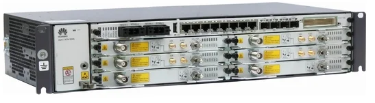
Figure 2-1 Appearance of the IDU 950A
ODU
The ODU is the outdoor unit for the OptiX RTN 900. It converts frequencies and amplifies signals.
The OptiX RTN 900 product series can use the RTN 600 ODU and RTN XMC ODU, covering the entire frequency band from 6 GHz to 42 GHz.
Table 2-2 RTN XMC ODUs that the OptiX RTN 950A supports
| Item | Description | ||
|---|---|---|---|
| High-Power ODU | |||
| ODU type | XMC-2 | XMC-2H | XMC-3 |
| Frequency band | 6/7/8/10/10.5/11/13/15/18/23/26/28/32/38/42 GHz | 6/7/8/11 GHz | 13/15/18/23/26/28/32/38 GHz |
| Highest-order Modulation |
2048QAM (13/15/18/23/38 GHz, 7/8 GHz XMC-2E)
1024QAM (6/10/10.5/11/26/28/32/42 GHz)
256QAM (7/8 GHz Normal)
| 2048QAM |
4096QAM (13/15/18/23/26 GHz)
2048QAM (28/32/38 GHz)
|
| Channel spacing |
3.5/7/14/28/40/50/56 MHz
NOTE:
The 10.5 GHz frequency band does not support 40/50/56 MHz channel spacing.
| 7/14/28/40/50/56 MHz |
3.5/7/14/28/40/50/56 MHz (13/15/18/23/38 GHz)
7/14/28/40/50/56 MHz (26/28 GHz)
7/14/28/40/50/56/112 MHz (32 GHz)
|
Table 2-3 RTN 600 ODUs that the OptiX RTN 950A supports
| Item | Description | |
|---|---|---|
| High-Power ODU | Standard Power ODU | |
| ODU type | HP, HPA | SP, SPA |
| Frequency band |
6/7/8/10/10.5/11/13/15/18/23/26/28/32/38 GHz (HP)
6/7/8/11/13/15/18/23 GHz (HPA)
|
7/8/11/13/15/18/23/26/38 GHz (SP ODU)
6/7/8/11/13/15/18/23 GHz (SPA ODU)
|
Highest-order
Modulation |
256QAM
|
256QAM
|
| Channel spacing |
7/14/28/40/56 MHz (6/7/8/10/11/13/15/18/23/26/28/32/38 GHz)
7/14/28 MHz (10.5 GHz)
| 3.5/7/14/28 MHz |
There are two methods for mounting the ODU and the antenna: direct mounting and separate mounting.
Figure 2-2 Direct mounting

Figure 2-3 Separate mounting

Product Features
1. Microwave Types
1) SDH Microwave
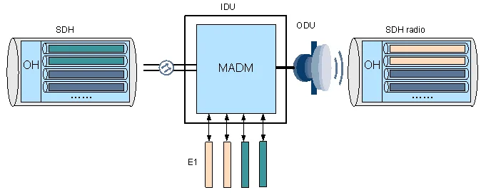
Unlike conventional SDH microwave equipment, the OptiX RTN 950A has a built-in MADM. The MADM grooms services to the microwave port through cross-connections, maps the services into the STM-1-based or 2xSTM-1-based microwave frames, and then transmits the frames. With this capability, services are flexibly groomed and the optical network and the microwave network are seamlessly converged.
Figure 3-1 SDH microwave
2) Hybrid/Packet Integrated IP Microwave
The Hybrid/Packet integrated IP microwave (Integrated IP radio for short) can transmit one type among or a combination of Native TDM services, Native Ethernet services, and PWE3 packet services according to software settings. Therefore, the Integrated IP radio achieves a smooth upgrade from Hybrid microwave to Packet microwave.
IP Microwave Classification
IP microwave can transmit packet services and support the AM function. The packet services transmitted can be Native Ethernet services or packet services encapsulated in PWE3. Conventional IP microwave is divided into two different types: Hybrid microwave and Packet microwave.
- Hybrid microwave: Native TDM services and Native Ethernet services can be transmitted through the air interface.
- Packet microwave: TDM services, ATM/IMA services, and Ethernet services after PWE3 encapsulation are transmitted through the air interface.
As IP microwave evolves, the OptiX RTN 950A supports Integrated IP radio. As a result, the equipment can support Hybrid microwave and Packet microwave at the same time, and can simultaneously transmit multiple types of services at air interfaces.
Integrated IP radio
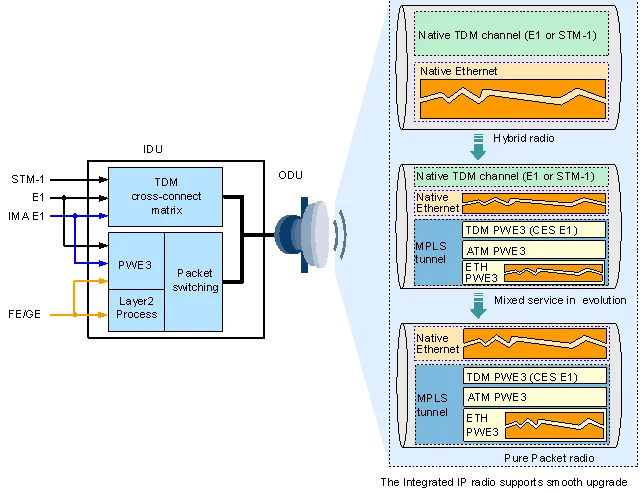
To achieve flexible grooming of TDM services and packet services on the Integrated IP radio, the OptiX RTN 950A is embedded with dual service planes: TDM service processing plane and packet service processing plane. TDM services and packet services can be flexibly transmitted over the Integrated IP radio, as shown in Figure 1.
- TDM service processing planePerforms cross-connections on the incoming TDM services (E1 services or STM-1 services), and transmits the services to the microwave ports.
- Packet service processing planePerforms PWE3 emulation on the incoming services (E1 services, ATM/IMA services, and Ethernet services), encapsulates them into the MPLS packets, and transmits the Ethernet frames that bear the MPLS packets to the microwave ports. However, Ethernet services can be directly transmitted to the microwave ports in Native mode after Layer 2 switching.
Native TDM services, MPLS packets, or Native Ethernet services need to be groomed to the microwave port, encapsulated into microwave frames, and then transmitted on microwave links. TheIntegrated IP radio serves as Hybrid microwave when TDM services are scheduled to the microwave port over the TDM service processing plane and Ethernet services are scheduled to the microwave port over the packet service processing plane; the Integrated IP radio serves as Packet microwave when TDM services are encapsulated into MPLS/PWE3 packets on the packet service processing plane and then scheduled to the microwave port.
Figure 3-2 Hybrid/Packet integrated IP microwave
The Hybrid/Packet integrated IP microwave has the following features:
- Transmits one, or several of the TDM services, MPLS/PWE3 services, and Native Ethernet services.
- Supports the AM function. E1 services and packet services can be configured with priority. When AM is switched to the reference mode, the services with higher priority are transmitted with preference.
2. Service Interfaces
The OptiX RTN 950A provides several service interfaces on the system control, switching, and timing board, and it is also able to provide a wide-assortment of service interfaces by configuring appropriate service interface boards.
Table 3-1 Types and number of service interfaces that the system control, switching, and timing board supports
| System Control, Switching, and Timing Board | Service Interface | Quantity |
|---|---|---|
| CSHO | GE electrical interface (RJ45): 10/100/1000BASE-T(X) | 4 |
GE electrical interface (SFP) or GE/FE optical interface (SFP):
| 2 | |
STM-1 electrical interface (SFP) or
STM-1 optical interface (SFP): Ie-1, S-1.1, L-1.1, and L-1.2
| 2 | |
| 75-ohm or 120-ohm E1 interface | 16 |
Table 3-2 Types and number of service interfaces that each service interface board supports
| Service Interface Board | Service Interface | Quantity |
|---|---|---|
| EG4 |
GE electrical interface (RJ45) or GE/FE optical interface (SFP):
| 2 |
| GE electrical interface (RJ45): 10/100/1000BASE-T(X) | 2 | |
| EG4P |
GE electrical interface (RJ45) or GE/FE optical interface (SFP):
| 2 |
GE electrical interface with power supply (RJ45): 10/100/1000BASE-T(X)
| 2 | |
| EFP8 | FE electrical interface (RJ45): 10/100BASE-T(X) | 8 |
| EMS6 | FE electrical interface (RJ45): 10/100BASE-T(X) | 4 |
GE electrical interface (SFP) or GE optical interface (SFP):
| 2 | |
| SP3S | 75-ohm or 120-ohm E1 interface | 16 |
| SP3D | 75-ohm or 120-ohm E1 interface | 32 |
| CQ1 |
Channelized STM-1 electrical interface (SFP) or
Channelized STM-1 optical interface (SFP): Ie-1, S-1.1, L-1.1, L-1.2, S-1.1-BX, L-1.1-BX
| 4 |
| SL1DA |
STM-1 electrical interface (SFP) or
STM-1 optical interface (SFP): Ie-1, S-1.1, L-1.1, L-1.2
| 2 |
| ML1 | 75-ohm or 120-ohm Smart E1 interface: supports CES E1, ATM/IMA E1, ML-PPP E1, and Fractional E1 | 16 |
| MD1 | 75-ohm or 120-ohm Smart E1 interface: supports CES E1, ATM/IMA E1, ML-PPP E1, and Fractional E1 | 32 |
3. Ethernet Service Processing Capability
Table 3-3 Ethernet service processing capability
| Item | Description |
|---|---|
| Ethernet service type |
|
| Range of maximum frame length |
1518 bytes to 9600 bytes
|
| VLAN |
|
| MAC address |
|
| Spanning tree |
Supports the MSTP protocol, and generates only the Common and Internal Spanning Tree (CIST). The functions of the MSTP protocol are equal to those of the RSTP protocol.
|
| Link aggregation (LAG) |
Applies to the FE/GE port and microwave port.
|
| Physical link aggregation |
Supports PLA and EPLA/EPLA+ fucntions.
PLA and EPLA/EPLA+ are Layer 1 link aggregation group (L1 LAG) technology, which shares load based on the bandwidth at the physical layer to achieve link aggregation. Physical link aggregation does not use the Hash algorithm and is independent of service flow compositions and therefore makes full use of link bandwidth.
|
| ERPS |
Supports ITU-T G.8032v1-compliant ring network protection for Ethernet services.
|
| LPT |
Disables the remote Ethernet port that is connected to the user equipment when the transmission network or local port fails.
|
| QoS | Supports QoS. For details, see QoS. |
| Traffic control function |
Supports the IEEE 802.3x-compliant traffic control function.
|
| ETH-OAM |
|
| Ethernet performance monitoring |
|
| Synchronous Ethernet |
Supports ITU-T G.8261- and ITU-T G.8262-compliant synchronous Ethernet.
|
| EoPDH | Supported. The EFP8 board provides the EoPDH function. |
| EoSDH | Supported. The EMS6 board provides the EoSDH function. |
Functions
Table 4-1 Functional units
| Functional Unit | Function |
|---|---|
| Service interface unit |
|
| Timeslot cross-connect unit | Provides the cross-connect function and grooms TDM services. |
| Packet switching unit |
|
| IF unit |
|
| Control unit |
|
| Clock unit |
|
| Auxiliary interface unit |
|
| Power unit |
|
| Fan unit |
Provides air cooling for the IDU.
|
| ODU |
|
IDU
Table 4-2 List of the IDU boards
| Board Acronym | Board Name | Valid Slot | Description |
|---|---|---|---|
| CSHO | Hybrid system control, switching, and timing board | Slot 7 |
NOTE:
The new SLF2CSHO board is hardware ready for L3VPN functions. SLF2 is the function version.
|
| ISU2 | Universal IF board |
Slot 1 to slot 6
|
|
| ISX2 | Universal XPIC IF board |
Slot 1 to slot 6
|
|
| ISV3 | Versatile IF board |
Slot 1 to slot 6
|
|
| ISM6 | Two-channel versatile IF board |
Slot 1 to slot 6
|
|
| IFU2 | Universal IF board |
Slot 1 to slot 6
|
|
| SL1DA | 2xSTM-1 interface board |
Slot 1 to slot 6
|
|
| CQ1 | 4-port channelized STM-1 interface board |
Slot 1 to slot 6
|
|
| EG4 | 2-port RJ45/SFP + 2-port RJ45 Gigabit Ethernet interface board |
Slot 1 to slot 6
|
|
| EG4P | 2-port RJ45/SFP + 2-port RJ45 Gigabit Ethernet interface board with the power supply function |
Slot 1 to slot 6
|
|
| EFP8 | 8-port RJ45 FE EoPDH processing board with the switching function |
Slot 1 to slot 6
|
|
| EMS6 | 4-port RJ45 and 2-port SFP FE/GE EoSDH processing board with the switching function |
Slot 1 to slot 6
|
|
| ML1 | 16xE1 (Smart) tributary board |
Slot 1 to slot 6
|
|
| MD1 | 32xE1 (Smart) tributary board |
Slot 1 to slot 6
|
|
| MN1 | Multiprotocol processing board |
Slot 1 to slot 6
|
|
| SP3S | 16xE1 tributary board |
Slot 1 to slot 6
|
Provides sixteen 75-ohm or 120-ohm TDM E1 interfaces.
|
| SP3D | 32xE1 tributary board |
Slot 1 to slot 6
|
Provides thirty-two 75-ohm or 120-ohm TDM E1 interfaces.
|
| AUX | Auxiliary interface board |
Slot 1 to slot 6
|
Provides one orderwire interface, one asynchronous data interface, one synchronous data interface, and four-input and two-output external alarm interfaces.
|
| TCU6 | 6xE1 connector conversion board | Slot 1 to slot 6 | Provides one DB44 connector and six RJ45 connectors. When being used with an E1 tributary board and an Anea 96 to DB44 transit cable, it converts E1 interfaces 1 to 6 on the Anea 96 connector into RJ45 connectors. |
| FAN | Fan board |
slot 11
|
Cools and ventilates the IDU.
|
ODU
The ODU is an integrated system that is available in several models. The architectures and working principles of the various ODU models are similar.
Block Diagram
Figure 4-1 Block diagram of the ODU
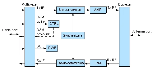
Signal Processing in the Transmit Direction
The multiplexer splits the signal from the IF cable into a 350 MHz IF signal, a 5.5 MHz O&M uplink signal, and a -48 V DC power signal.
In the transmit direction, the IF signal is processed as follows:
- After the up-conversion, filtering, and amplification are completed, the IF signal is converted into the RF signal and then is sent to the AMP amplifier unit.
- The AMP amplifies the RF signal (the output power of the signal can be controlled by the IDU software).
- After the amplification, the RF signal is sent to the antenna through the duplexer.
The O&M uplink signal is a 5.5 MHz ASK-modulated signal and is demodulated in the CTRL control unit.
The -48 V DC power signal is sent to the PWR power unit where the secondary power supply that uses a different voltage is generated and provided to the modules of the ODU.
Signal Processing in the Receive Direction
The duplexer separates the RF signal from the antenna signal. The RF signal is amplified in the low noise amplifier (LNA). After the down-conversion, filtering, and amplification are completed, the RF signal is converted into the 140 MHz IF signal and then is sent to the multiplexer.
The O&M downlink signal is modulated under the ASK scheme in the CTRL unit. The 10 MHz signal is generated through the modulation and is sent to the multiplexer. The CTRL unit also detects the received signal power through the RSSI detection circuit and provides the RSSI interface.
The IF signal and the O&M downlink signal are combined in the multiplexer and then are sent to the IDU through the IF cable.
 Posted in: Knowledge Sharing


0 comments:
Post a Comment